目录
回顾
上一篇,我们讲到了以下内容,在回顾一下。
- 16-bit Real Mode 是 x86 系列 CPU 的一种工作模式,所有 x86 系列 CPU 启动时,都处于 16-bit Real Mode
- 16 bit 系统中,只有 64 KB 内存可以被识别,CPU 一次只能处理 16 bit 的数据
- 8086 架构,因为有 20 bit 的地址总线,所以寻址总量有 1 MB
- 8086 架构的内存管理采用内存分段机制,内存分段将程序不同的部分加载到不同的不连续的内存中
- 16-bit Real Mode 真实物理地址的计算公式为:物理地址 = 段地址左移 4 位 + 偏移地址
- 中断可以让 CPU 暂时停止当前任务,执行我们指定的任务,然后回去执行原先的任务
- 中断在 interrupt vector 中由一个数值做索引,interrupt vector 包含 interrupt service routines 的内存地址
- 第一个 Hello World 程序使用中断,在屏幕上显示 HelloWorld 字符串
今日目标
本篇,我们将结束 16-bit Real Mode 的内容,储备更多的知识,为下一篇开启 32-bit Protected Mode 做准备。
本篇内容主要以汇编代码为主,讲解一些必要的指令。我们会从一个打印 16 进制字符串的程序开始,将
- boot sector 与内存的关系
- 字符串定义
- 堆栈的使用
- 方法调用
- 条件跳转
- 文件包含
- 物理内存寻址
- 中断读取磁盘数据
这些内容一一覆盖到。
Boot Sector 与内存的关系
我们从研究 boot sector 程序与内存的关系开始。
回想之前,计算器启动,BIOS 做自检(专业术语叫 POST - Power-On Self-Test,详见这篇文章),然后读取存储介质上的前 512 个字节,如果 0x55 和 0xaa 出现在第 510 和 511 个字节上,BIOS 就认为这是一个正规的 boot sector,开始执行其代码,然后加载操作系统。
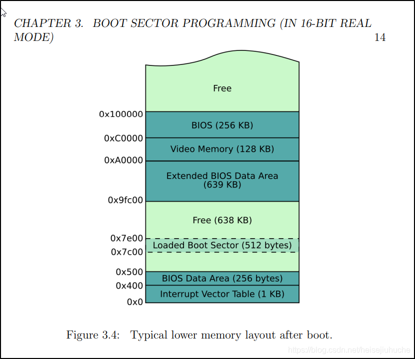
一切程序的执行,第一步要将程序加载到内存。那么 boot sector 被 BIOS 加载到内存的那一部分呢?
首先,肯定不是整个内存的起始位置(0x0)。因为之前说过,远在 BIOS 寻找 boot sector 之前,就已经做开始检测硬件等的操作。想必有一些必要的指令,已经被加载到内存最初的位置上。另外,还记得 interrupt vector table 以及 interrupt service routines (ISRs),这些都必须首先存在于内存,我们在 boot sector 中才有能力去调用中断,做相应的操作。
书中说,boot sector,会被 BIOS 固定加载到 0x7c00 这个位置上。
直接引用书上的内存示意图(来源:https://www.cs.bham.ac.uk/~exr/lectures/opsys/10_11/lectures/os-dev.pdf)。

原书中作者写着写着打了一个问号在这里。本着怀疑一切的态度,我们要证实一下,boot secotr 是不是被加载到了 0x7c00 这个位置。

打印任意内存位置上的内容(以 16 进制输出)
我们有能力打印字符(上一个 HelloWorld 程序),那么要证实 boot sector 被加载到 0x7c00,只需要打印出该内存地址开始的连续一些字节,和 od 命令的输出做比对,就能知道书中是否正确。记住 16-bit Real Mode 下内存没有保护机制,所以,是可以访问或者写入到任意内存,目前也没有什么后果,大家可以自行尝试。
这里的关注点不要放在代码上,后面会对代码做深入讨论。
打印 16 进制的代码在 @cfenollosa 的 Github 上能找到。这里需要两个文件,一个是 print 方法,负责打印字符串,另一个,是 print_hex 方法,负责转换 16 进制数为字符串,然后调用 print 来打印。
print.asm:
print:
    pusha

; keep this in mind:
; while (string[i] != 0) { print string[i]; i++ }

; the comparison for string end (null byte)
start:
    mov al, [bx] ; 'bx' is the base address for the string
    cmp al, 0
    je done

    ; the part where we print with the BIOS help
    mov ah, 0x0e
    int 0x10 ; 'al' already contains the char

    ; increment pointer and do next loop
    add bx, 1
    jmp start

done:
    popa
    ret

print_nl:
    pusha

    mov ah, 0x0e
    mov al, 0x0a ; newline char
    int 0x10
    mov al, 0x0d ; carriage return
    int 0x10

    popa
    ret
print_hex.asm:
; receiving the data in 'dx'
; For the examples we'll assume that we're called with dx=0x1234
print_hex:
    pusha

    mov cx, 0 ; our index variable

; Strategy: get the last char of 'dx', then convert to ASCII
; Numeric ASCII values: '0' (ASCII 0x30) to '9' (0x39), so just add 0x30 to byte N.
; For alphabetic characters A-F: 'A' (ASCII 0x41) to 'F' (0x46) we'll add 0x40
; Then, move the ASCII byte to the correct position on the resulting string
hex_loop:
    cmp cx, 4 ; loop 4 times
    je end

    ; 1. convert last char of 'dx' to ascii
    mov ax, dx ; we will use 'ax' as our working register
    and ax, 0x000f ; 0x1234 -> 0x0004 by masking first three to zeros
    add al, 0x30 ; add 0x30 to N to convert it to ASCII "N"
    cmp al, 0x39 ; if > 9, add extra 8 to represent 'A' to 'F'
    jle step2
    add al, 7 ; 'A' is ASCII 65 instead of 58, so 65-58=7

step2:
    ; 2. get the correct position of the string to place our ASCII char
    ; bx <- base address + string length - index of char
    mov bx, HEX_OUT + 5 ; base + length
    sub bx, cx  ; our index variable
    mov [bx], al ; copy the ASCII char on 'al' to the position pointed by 'bx'
    ror dx, 4 ; 0x1234 -> 0x4123 -> 0x3412 -> 0x2341 -> 0x1234

    ; increment index and loop
    add cx, 1
    jmp hex_loop

end:
    ; prepare the parameter and call the function
    ; remember that print receives parameters in 'bx'
    mov bx, HEX_OUT
    call print

    popa
    ret

HEX_OUT:
    db '0x0000',0 ; reserve memory for our new string
利用 cfenollosa 代码,我们写一个简单的测试代码:
boot_sect_mem_chk.asm
org 0x7c00
mov dx, [0x7c00] ; 将内存地址 0x7c00 位置上的数据,写入到 dx 寄存器
call print_hex ; 调用 print_hex 方法输出 dx 中的内容

jmp $  ; 跳转到当前地址(无限循环)

%include "print.asm"
%include "print_hex.asm"

times 510 - ($ - $$) db 0 ; 512 个字节中剩余字节全部填充 0
dw 0xaa55 ; 最后一个字节,是 0xaa55,让 BIOS 知道这是 boot sector
编译:
nasm -f bin boot_sect_mem_chk.asm -o boot_sect_mem_chk.bin运行:

与 od 命令的输出做对比:
od -t x1 -A n boot_sect_mem_chk.bin
证实了 boot sector 被加载到 0x7c00 内存的说法。大家可以将 mov dx, [0x7c00] 中的内存地址依次 +2,输出与 od 命令是完全一致的。不要忘了,x86 架构是小字节序,QEMU 中打印出来的每个字节,与 od 命令显示的是相反的。
物理寻址的应用
前一篇文章铺垫了很多关于 8086 架构物理地址计算的信息,现在,该尝试一下在代码中做应用,加深理解。
段寄存器(Segment Register)和索引寄存器(Index Register)
回忆一下前一篇文章也说过,一些寄存器是搭配使用的,我们先回顾一下。
8086 CPU 有 4 个段寄存器,分别是:
- Code Segment Register (CS) - 用来指向代码段在内存中的基地址
- Data Segment Register (DS) - 用来指向数据段在内存中的基地址
- Extra Segment Register (ES) - 额外的数据寄存器
- Stack Segment Register (SS) - 用来指向堆栈段在内存中的基地址
与其相匹配的,有四个索引寄存器(直接按照英文意译了),这 4 个索引寄存器
- IP 与 CS 寄存器配合,包含代码在代码段内存中的偏移量
- SI 与 DS 寄存器配合,包含数据在数据段内存中的偏移量
- DI 与 ES 寄存器配合,包含数据在数据段内存中的偏移量
- SP 与 SS 寄存器配合,包含变量在栈段内存中的偏移量
找到 Boot Sector 在内存中的第一个字节的位置
我们还是拿 boot_sect_mem_chk.asm 举例,顺便开始讲解一些必须知道的汇编指令。
我们的目标是,用前文所说的寄存器,换一种方式来找到 Boot Sector 的第一二个字节的内容,打印出来。
org 0x7c00
mov dx, [0x7c00] ; 将内存地址 0x7c00 位置上的数据,写入到 dx 寄存器
call print_hex ; 调用 print_hex 方法输出 dx 中的内容

jmp $  ; 跳转到当前地址(无限循环)

%include "print.asm"
%include "print_hex.asm"

times 510 - ($ - $$) db 0 ; 512 个字节中剩余字节全部填充 0
dw 0xaa55 ; 最后一个字节,是 0xaa55,让 BIOS 知道这是 boot sector
拆解一下程序,然后逐步展开:
【1】:org 指令,明确告诉 assembler 我们的 Boot Sector 代码被加载到 0x7c00 的位置
【2】:mov 指令,将相对于 0x0,偏移量为 0x7c00 内存位置上的值写入 dx
【3】:调用 print_hex 方法,打印出 dx 寄存器中的值
【4】:挂起 CPU
【5】【6】:包含两个打印方法的文件
【7】:除去该行指令以上所有指令的长度,除去最后两个字节的长度,其余位置全部填充 0
【8】:最后两个字节固定值,0xaa55
开始展开。
org 指令有什么作用
org 指令,明确告诉 assembler 我们的 Boot Sector 代码被加载到 0x7c00 的位置。范范这么一句话,感觉什么都没有讲明白。
我们用代码来说明一下,使用了 org 之后,有什么作用。
org 使用之后,ds 寄存器的值是 0x0,si 寄存器的值是 0x0,
第 2 行 mov dx, [0x7c00] 中括号中的值,是相对于 ds 的偏移量。

- https://wiki.osdev.org/Boot_Sequence
- https://www.cs.bham.ac.uk/~exr/lectures/opsys/10_11/lectures/os-dev.pdf
- https://nets.ec/Ascii_shellcode
- https://thestarman.pcministry.com/asm/debug/Segments.html
- https://www.tutorialspoint.com/assembly_programming/assembly_registers.htm
- http://dewkumar.blogspot.com/2012/01/what-is-org-origin-directive-in.html#:~:text=What%20is%20ORG%20(origin)%20directive%20in%20assembly%20level%20language%3F,expression%20in%20the%20operand%20field.
- https://stackoverflow.com/questions/38318230/how-to-display-register-value-using-int-10h
- https://en.wikipedia.org/wiki/INT_13H#INT_13h_AH.3D02h:_Read_Sectors_From_Drive
- https://stackoverflow.com/questions/50260277/is-there-a-difference-between-org-0x7c00-and-mov-ax-07c0h
- https://thestarman.pcministry.com/asm/2bytejumps.htm
- http://ps-2.kev009.com/wisclibrary/aix52/usr/share/man/info/en_US/a_doc_lib/aixassem/alangref/absolute_add.htm